
Precision Timer for Cortex
General Description
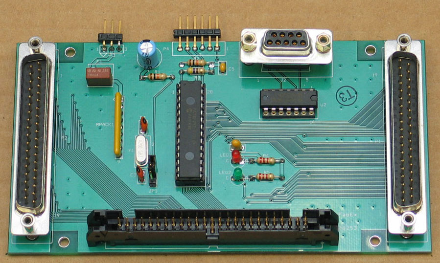
The Precision Timer for Cortex is a circuit board and software for generating precisely timed pulses. The pulses can be programmed from 2 microseconds (µs) to 2 seconds. The pulse can be monitored by Cortex and used for timing within a Cortex program. The Precision Timer circuit board (above) requires one entire 24-bit DIO port (Ports A, B and C). The circuit board has a 37-pin connector for use with a CIO-DIO24, CIO-DIO96, PCI-DIO24 or PCI-DIO24H. The board also has a 50-pin connector for use with a CIO-DIO48, PCI-DIO48H, PCI-DIO48H-RT, PCI-DIO96, PCI-DIO96H. (The 50-in connector is not compatible with a PCI-DAS1602/12.) When using the 50-pin connector (which supports 2 DIO ports), the unused DIO port is split-out to a spare 37-pin connector. (See details below.) Note that not all versions of Cortex support all the above-listed boards.
Cortex Software
The software for the Precision Timer runs under Cortex. The subroutines written for the Timer are complex, but using the subroutines is easy. Here is an example for delivering a 450 µs pulse. In this example, Cortex delivers the pulse and then waits until the pulse is complete.
PRECISION_TIMERset( .45, 1); // set timer to 0.45ms. Enable output number 1
PRECISION_TIMERstart(); // start the pulse
while(!PRECISION_TIMERdone); // wait for the pulse to end
The above commands require certain hardware and other definitions in the Cortex state file. The following sections describe proper software setup.
Hardware definitions
Here are some definitions that work for most DIO devices. This example assumes the DIO device is the second DEVICE listed in the CORTEX.CFG file. Insert this code before main() in the state file. Put the subroutines at the end of the state file. A link to download the subroutines is at the bottom of this page.
// PTIMER definitions
// The precision timer requires a dedicated DIO device defined in CORTEX.CFG
// Device initialized as: PORTS A, B C(high)=outputs, C(low)=inputs
#define PTIMER_DEV 1 /* CORTEX.CFG device number */
#define PTIMER_BASE 0x00 /* Offset of PORTA in device register map */
#define PTIMER_PORTA PTIMER_BASE
#define PTIMER_PORTB PTIMER_BASE+1
#define PTIMER_PORTC PTIMER_BASE+2
#define PTIMER_CTRL PTIMER_BASE+3
#define PTIMER_DEV_INIT DEVoutp(PTIMER_DEV,PTIMER_CTRL,0x81)
#define PTIMER_SET_COUNT 0x10
#define PTIMER_TRIGGER 0x20
#define PRECISION_TIMERdone !(DEVinp(PTIMER_DEV,PTIMER_PORTC) & 0x01)
#define PTIMER_CHAN1 0x10
#define PTIMER_CHAN2 0x20
#define PTIMER_CHAN3 0x30
#define PTIMER_CHAN4 0x40
// Globals needed for the Precision Timer
#define PRECISION_TIMER_WAIT_COUNT _int29 /* there are 30 integers, any will do */
#define PRECISION_TIMER_MS_TIMER 30 /* there are 32 timers, any will do */
// Functions needed for the Precision Timer (put the actual functions at the end of the state file)
int PRECISION_TIMERset(float ptimer_duration, int ptimer_channels);
int PRECISION_TIMERready() ;
void PRECISION_TIMERstart();
void PRECISION_TIMERchan(int ptimer_channels);
void PRECISION_TIMERabort();
void PRECISION_TIMERwait(int PT_wait_count);
int PRECISION_TIMERcalibrate();
// main() { goes here }
//
// Then your own subroutines
// Then the Precision Timer subroutines
Connecting the Precision Timer Circuit Board
The circuit board has four connectors and three headers. The three largest connectors are two 37 pin D-subminiature connectors and a 50 pin ribbon connector. These three connectors can be used in various ways:
1. The 37 pin connector on the right (P1) can connect directly to any DIO board that has a 37 pin output (e.g., CIO-DIO24 or PCI-DIO24).
2. The 50 pin connector can be used with any DIO board that uses a 50 pin connector (e.g., PCI-DIO48H, PCI-DIO96). These 50 pin connectors always supply connections for two 24-bit DIO ports. Since the Precision Timer only uses one of the two ports, the 37 pin connector on the left side of the board (P2) can be used to access the unused 24-bit DIO port.
3. It is possible to assemble a board with only these three connectors, and no other parts. In this case the board is not used a a timer, but can be used to convert a 50 pin connection to two 37 pin connections.
The smaller, 9 pin D-subminiature connector is the output connector. The Precision Timer has two types of outputs, unmasked and masked. The pin connections are:
Pin 1 unmasked pulse output
Pin 2 masked pulse 1 output
Pin 3 masked pulse 2 output
Pin 4 masked pulse 3 output
Pin 5 masked pulse 4 output
Pin 9 ground
When a pulse is produced it is always available at the unmasked pulse output. It is also available at any or all of the other outputs, depending on the current mask value.The mask is set when the timer is set (PRECISION_TIMERset) or with the PRECISION_TIMERchan() command. Masked outputs allow you to control multiple devices with one pulse generator. For example, two masked output could each control different solenoids for fluid delivery. Masking determines which fluid will be delivered. Each channel is listed in the command:
PRECISION_TIMERchan(PTIMER_CHAN1 | PTIMER_CHAN2 | PTIMER_CHAN3 | PTIMER_CHAN4);
The vertical bar is a logical OR function. Use it to enable the channels you want active. Unlisted channels will be turned off. The command acts immediately, so you could change outputs in the middle of a pulse. You probably want to avoid doing so.
Calibrating the Precision Timer
The Precision Timer must be calibrated at least once each time Cortex is run. Fortunately, calibration is quick and easy.
PRECISION_TIMER_WAIT_COUNT = PRECISION_TIMERcalibrate();
if (PRECISION_TIMER_WAIT_COUNT > 100) Mprintf(1,"CALIBRATE ERROR");
The variable PRECISION_TIMER_WAIT_COUNT is defined as a persistent variable (see above). A calibration error indicates there is a configuration problem. Once the board is connected and running properly, the value of PRECISION_TIMER_WAIT_COUNT will be between 2 and 20. The calibration makes certain your computer talks to the Precision Timer as fast as possible without introducing errors.
Building and Testing a Precision Timer Circuit Board
The Precision Timer circuit board only has about 25 parts and is easy to construct. Because we are looking for people to test the current version, we have boards to distribute without charge. One component, the PIC microprocessor chip must be programmed before the board will work. If you are not set up to program a PIC processor, send an email to the webmaster to arrange programming. The firmware is available both as source code and object files (see below). If you are not programming the PIC processor yourself, do not bother with headers P2 or P3. P2 is for external power and P3 is for PICkit2 programmer. Do install the JP1 header; it is used for testing. To test the timer board and PIC processor, place a jumper on JP1 before turning on your computer. Connect the DIO board and then turn the computer on. When the board senses power the red and green LEDs with flash in an alternating pattern. Once you see the alternating pattern, power down the computer and remove the jumper. If the LEDs do not flash there is a problem with the PIC processor, the connection to the DIO board, or the installation of the parts on the board. Check to be sure the capacitors C1 and C2 are not wired backwords, that the integrated circuits are oriented properly, and that the resistor RPACK1 is oriented correctly. Often, the LEDs are wired backwards. To test the LEDs, remove the PIC processor and DIO board connections. Use a 9 volt battery (or 5 volt to 9 volt power supply). Connect the positive to Pin 20 of the PIC processor socket on the circuit board. Connect the negative to either pin 17 (for green LED) or pin 18 (for red LED). If the LEDs do not light up, try reversing the battery leads. If reversing the battery leads works, the LEDs are wired backwards.
Using the Precision Timer
PCXTEST2.C is provided as an example of how to use the Precision Timer. Here are some valuable guidelines.
- Use JP 1 to make sure the board works properly.
- Make sure the hardware is connected properly.
- Make sure the jumper JP1 is removed before trying to use the Precision Timer.
- Make sure the state file has the necessary hardware, global variable definition, timer definition, and subroutines.
- Run PTIMER_DEV_INIT at least once to configure the DIO port.
- Run PRECISION_TIMERcalibrate(), make sure the value is below 100, and use the value to set PRECISION_TIMER_WAIT_COUNT.
- If possible, set the timing period with PRECISION_TIMERset() before you need to deliver a pulse. There is a small delay associated setting the timer.
- If the timer has already been set, PRECISION_TIMERstart() is executed very quickly, within a few microseconds.
- Mix the use of Cortex timers with the Precision Timer for flexibility. See the Pulse Train Test in PCXTEST2.C for an example.
- You may need a buffer circuit if the Precision Timer must drive a circuit that takes extra current or is connected through a long cable.
Specifications and Technical Information
Resolution and Accuracy
Accuracy is fixed. Resolution depends upon range. Range is selected automatically for maximum resolution.
| Range | Resolution | Accuracy |
| 0.002 ms to 2.053 ms | 2 µs | 2 µs |
| 2.053 ms to 20.53 ms | 20 µs | 2 µs |
| 20.53 ms to 205.3 ms | 200 µs | 2 µs |
| 205.3 to 2046 ms | 2 ms | 2 µs |
PIC Firmware and communications with the PC
Firmware for PIC processor is programmed using the Microchip tools: MPLAB (V8.14) and PIC32 C-compiler. The Cortex computer supplies a 4-bit range value and a 10-bit count using a somewhat complicated algorithm to optimize resolution on the PIC processor. These values are sent as a parallel control word to the PIC. At the pic, the values are translated into a 4-bit prescale value and a 16-bit count for TIMER0. No interrupts are used. The PIC preloads the timer count and waits in a tight loop for a Start command. Once started, the PIC waits in a tight loop for either an Abort command or an overflow of the counter. The firmware can be recompiled for various test mode patterns. The default pattern is to flash the two on-board LEDs in an alternating pattern, but there are seven other test modes. The test mode is activated when the board is powered up with jumper JP1 in place.
To send the 10-bit count word and 4-bit range value from the PC, there are two additional handshaking bits. The PIC provides a Ready Flag and the PC sends a Set Count flag. When the PC sets the Set Count Flag, it must pause before checking for the Ready Flag to clear. The pause is controlled by the PRECISION_TIMERwait() function, which just runs a dummy loop to kill time. The amount of looping is controlled by the PRECISION_TIMER_WAIT_COUNT variable, which is set during the calibration step. PRECISION_TIMERcalibrate() raises and lowers the Set Count Flag over and over, while testing different delay values. It watches the Ready Flag and searches for a minimum delay time using a series of error criteria and a safety margin.
The DIO board of the PC is initialized with both Ports A and B as output ports. Port A and two bits from Port B make up the 10-bit count word. The remaining six bits of Port B are for two range bits and the 4-bit mask for the masked outputs. Port C is split, with the lower half used as an output for the Set Count Flag and the upper half as inputs for the Ready Flag. Another Port C input bit can monitor the output pulse of the PIC.
Circuit Board
Power for the Precision Timer Board is normally supplied by the NIMH Cortex DIO board. However, header P3 can supply power to the board for testing without any connection to the computer. Header P4 is a standard in-circuit programming connector for use with a PICkit2 in-circuit debugger/programmer.
The circuit board can be used as a breakout box/converter for 50 pin DIO connectors. If assembled with P1, P2 and J1 only, a 50 pin cable can be split out to two 37 pin connectors.
The circuit board can be assembled using only the needed connectors. For example, a DIO that only uses a 37 pin connector (e.g., CIO-DIO24) only needs P1. P2 and J1 can be omitted. P3 and P4 are only useful for programming and testing. Most users can omit them. The extra holes for fuse F1 are to let the user replace a bad fuse by cutting off the old one and inserting a new one in the unused holes.