

Plexon to Cortex file conversion program: mgplx2ctx
Overview
mgplx2ctx is a MATLAB program that converts Plexon .PLX files to NIMH Cortex file format. MatOFF and many other data analysis tools can read and process data in this format. This program is useful for researchers who have used NIMH Cortex in the past and wish to retain existing analysis software tools after switching data acquisition from NIMH Cortex to a Plexon, Alpha-Omega or Tucker Davis Technologies (TDT) system. NIMH Cortex is typically used to control the experiment and pass event codes through a digital I/O port to a data acquisition system. .PLX files created by Plexon, Alpha-Omega or TDT, can be used directly, or can be used after spike sorting with Off Line Sorter (Plexon, Inc.). .PLX files converted by mgplx2ctx end up in standard Cortex file format. mgplx2ctx is distributed with the MatOFF data analysis package. Unlike MatOFF, mgplx2ctx will not work with older versions of MATLAB; it requires MATLAB 2007a or later. mgplx2ctx uses the Plexon MATLAB Client Development Kit (CDK) to read .PLX files into MATLAB variables. Note, MATLAB R2009a and later use a new dynamic linked library (DLL) model and that requires an updated Plexon CDK.
Only part of the CDK is used for mgplx2ctx, and some new CDK-related functions have been added to aid analog data analysis. The new functions include, (1) a special version of the A/D read command that handles non-integer sample rates. AlphaLab (unlike Plexon MAP) can collect data with non-integer sample rates, so a new A/D read command "defragments" the .PLX file analog data and calculates the correct floating point sample rate; (2) functions that allow the user to extract analog data from a .PLX file, modify it, and then store the modified analog in a special MATLAB .MAT file. The new CDK-related functions read from this .MAT file (called an "external analog file") just like the CDK routines read from a .PLX file. Moreover, the new functions allow you to write to this .MAT file. One limitation of the Plexon CDK is that you cannot write data back to a .PLX file. The new CDK-related functions circumvent this limitation. After you copy analog data to the .MAT, you can read from and write to this .MAT as much as you like, including replacing or adding new analog channels. In general, we keep the two files together by using the same file name, just different extensions (.PLX and .MAT). mgplx2ctx and any other MATLAB analysis tool can read and process data from either or both files. The only difference is choosing which CDK function call to use. We choose our analog channel numbers so that channels in the .MAT file simply look like a continuation of the channels in the .PLX file.
The mapping file
Differences between the .PLX file structure and Cortex file structure dictate the use of a mapping file when running mgplx2ctx. Plexon files contain a continuous data stream with specialized data headers for each type of data encountered. The mgplx2ctx map file provides instructions for breaking this continuous stream in to NIMH Cortex files and trials, and supplies a correspondence between Plexon spike and analog channels with Cortex data channels.
An example mgplx2ctx mapping file is provided with this distribution. It is called mgplx2ctx.map, and it is well annotated.
Comments in the mapping file
A line beginning with a semicolon ";" is a comment in the mapping file.
File and trial mapping
NIMH Cortex files that are related to each other have the same file name and sequential file extension numbers (e.g., FILE.1, FILE.2, FILE.3, etc.). Within any one of these files, the data are divided into trials. Plexon files (.PLX) are continuous files that may include many trials and experimental conditions. Thus, a single Plexon file could be mapped to multiple NIMH Cortex files, and each of these Cortex files will generally have many trials. mgplx2ctx uses event codes to signal the start and end of each Cortex file and each Cortex trial. This scheme requires that experimenter has included these event codes in the data stream stored in the Plexon as file as "strobed events". Analog data stored in extended analog files (see above) are retrieved from .MAT files, but treated as if they come from .PLX files of the same name.
PLEXONSTART / PLEXONSTOP event codes
To break a Plexon file into multiple Cortex files, specify PLEXONSTART and PLEXONSTOP values in the map file. PLEXONSTART specifies the event used to indicate the beginning of a new NIMH Cortex file. PLEXONSTOP specifies the event used to indicate the end of a Cortex file. Any data between a PLEXONSTOP event code and the following PLEXONSTART event code will be ignored. Either PLEXONSTART or PLEXONSTOP can be set to zero. If both are set to zero, mgplx2ctx will simply create a single Cortex file.
Example:
PLEXONSTART: 990
PLEXONSTOP: 991
In this example, any data before event code 990 will be ignored. Following the first 990, data will be placed into a Cortex file until event code 991 is encountered. After that, a new event code 990 will make mgplx2ctx open a new Cortex file (adding +1 to the file extension number) and repeat the process.
CORTEXSTART / CORTEXSTOP event codes
NIMH Cortex files must be broken into trials using the CORTEXSTART and CORTEXSTOP event codes. mgplx2ctx will start a new trial in the Cortex file whenever it encounters the CORTEXSTART event code. The trial is ended when a CORTEXSTOP event is reached. If you set CORTEXSTOP to zero, CORTEXSTART will both end the previous trial and start a new one.
Example:
CORTEXSTART: 19
CORTEXSTOP: 20
This mapping file entry tells mgplx2ctx to start a new Cortex trial each time event code 19 occurs and end the trial at event 20. Events after event 20, but before the next occurrence of code 19, will not be stored.
ANALOGSTART / ANALOGSTOP event codes
mgplx2ctx will start moving analog data into the EOG buffer of the NIMH Cortex file when the ANALOGSTART event code is first found in a trial. Analog data will be added until the buffer is full, the CORTEXSTOP event is reached, or until the ANALOGSTOP event code is reached. The EOG buffer is designed to hold two 16-bit channels (called x and y) in the format: x,y,x,y,x,y... Thus, the buffer is filled in 4 byte steps. The Cortex trial header has a buffer size entry. That entry is a 16 bit unsigned integer (maximum value of 65,535). With 4 bytes per x-y entry, the maximum size will be 16,383 x-y entries. For example, at a sample rate of 1,000 samples/second, the buffer can hold 16.383 seconds of data before the pointer limit is reached. EPP data are stored in a separate buffer. EPP data can have from 0 to 15 channels, because a 4 bit channel number is appended to each 12 bit data value. The pointer for the EPP buffer limits that buffer to 65,534 A/D samples. At 1,000 samples/second, only about 6.5 seconds of data can be stored if there are 5 EPP channels. However, there is no restriction to have the same sample rate for all data in the EPP buffer. By down-sampling the data rates (via decimation), a group of slower analog signals can easily fit into the buffer. Since each sample has a channel marker, there is no set arrangement of the samples except that samples from any given channel be in order. mgplx2ctx inserts the data from each EPP channel separately so that all data from one channel is inserted before any data from the next channel. The time stamp for the first sample for every channel is the ANALOGSTART time.
If ANALOGSTOP is not used (set to zero or set to an event code value not in the data file), each ANALOGSTART after the first one will act as an ANALOGSTOP followed by an ANALOGSTART command.
Mapping Plexon spike events to Cortex event codes
Plexon and NIMH Cortex use very different methods for mapping spike channels. Plexon spike channels are stored as electrode number and the template number. Cortex treats each spike as an event code. The mgplx2ctx map file assigns a Cortex event code to each Plexon electrode and template using the S command:
; event code mapping for electrode #1
S 1,0: 0
S 1,1: 111
S 1,2: 112
S 1,3: 113
; event code mapping for electrode #2
S 2,0: 0
S 2,1: 114
S 2,2: 115
S 2,3: 116
In this example, the following assignments take place:
electrode #1
template 0 (unsorted spikes) is not mapped because it is assigned an event code value of zero
templates 1 to 3 are mapped to event codes 111 to 113
electrode #2
template 0 (unsorted spikes) is not mapped because it is assigned an event code value of zero
templates 1 to 3 are mapped to event codes 114 to 116
It is up to the user to prevent overlap between strobed event codes and spike events. If event codes 111 to 116 are in use as strobed events, do not map these event codes to spike channels.
Mapping Plexon Analog channels to Cortex EOG and Cortex EPP channels
EOG Channels (A command)
Plexon "slow analog" channels are mapped in a way similar to spike channels. Plexon channel numbering starts at channel 1. Only two channels are supported by the Cortex EOG buffer. These channels are traditionally used for X-Y eye position data. In Cortex, X and Y data must both be included an EOG buffer and they must have the same sample rate. In the example below, the Plexon channels 3 and 4 are mapped to Cortex X and Y eye data, respectively. (For historical reasons, Cortex channels 3 and 4 are the EOG channels.) The entry begins with the A command and then has the Plexon channel number followed by the Cortex channel number. Other channels can be mapped, but they will not be converted in any way. Mapping unused channels can be helpful when using the Evaluate function of mgplx2ctx.
mgplx2ctx is smart enough to help enforce the rules for analog channel mappings. It will balk if the user tries to map two different Plexon channels to the same Cortex channel. It will recognize if only one EOG channel is mapped, and produce a psuedo second channel with all zeros. It will also recognize (and complain) if the two mapped channels have different sample rates, or different decimation values (see below).
mgplx2ctx can decimate the EOG channels. Decimation, in this sense, is to select every 2nd, 3rd, 4th... sample, which effectively reduces the sample rate. The Plexon can collect analog at high sample rates into large buffers, but the Cortex buffer size is limited (see above). Down-sampling through decimation is a method to cope with the buffer size limitation of Cortex files. The EOG channel decimation value is set using a third parameter in the mapping file.
; Plexon channels 1 and 2 mapped to Cortex EOG channels (3 and 4), and they are
; downsampled to half of the original Plexon sample rate
A 1 : 3 : 2
A 2 : 4 : 2
EPP Channels (E command)
Up to 15 Plexon channels may be mapped to the EPP buffer. However, the EPP buffer can only hold a maximum of 32,767 samples. This small buffer size sets a practical limit on the number of data channels and their sample rates. The EPP buffer is ideal for very slow signals, like GSR (Galvanic skin resistance) or integrated EMG. Faster signals are fine as long as the total buffer length is not exceeded. A mixture of different sample rates for each channel is fine. To support a variable number of channels and a mixture of sample rates, each sample is tagged with a 4 bit channel number. The samples are 12 bit values shifted left by 4 bits. The 4 low order bits hold the channel number. Note that the two Plexon channels stored as EOG channels can also be stored as EPP channels.
Since most Plexon recording systems use one sample rate for all channels, even slow data are collected at the same rate as the fastest channel. Thus, even if GSR data only needs a 10 Hz data rate, it may be stored in the Plexon file at 1000 Hz to accomodate eye position data. mgplx2ctx supports decimation (see above) on a channel-by-channel basis Unlike the EOG buffer, where decimation is specified in the user interface, the decimation rates for EPP channels are specified in the E command. In the example below, Plexon channels 3 to 5 are stored into EPP channels 5 to 7. Plexon channel 5 is decimated 10:1 (saving every 10th sample) before being stored in Cortex channel 7. The decimation parameter is optional. Leaving it blank (or using a value of 1) will use every sample.
; Plexon : Cortex : Decimation
E 3: 5
E 4: 6
E 5: 7 : 10
External Channels (X command)
By taking advantage of the extended Plexon CDK (see Overview, above), mgplx2ctx can read analog data that has been extracted from a .PLX file, processed, and stored in a special .MAT file. These external analog data are tagged in the mapping file with the X command, but otherwise look and act like EPP channels.
; External channels
; Plexon : Cortex : Decimation
X 6: 8 : 100
X 7: 9 : 100
In this case, two channels that look to be channels 6 and 7 from a Plexon data file will be decimated 100:1 (e.g., 1000 Hz to 10 Hz sample rate), then stored as Cortex channels 8 and 9.
Using the program graphical user interface (GUI)
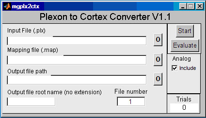
Typing mgplx2ctx on the MATLAB command line launches the window shown above. It is helpful to have the MATLAB path set to the data directory before starting mgplx2ctx. The user can enter data and mapping file names directly, or use a directory helper program by pressing a button marked "0". Input file and a mapping file names are required. To create an output file, enter the path to a directory for the output file path, and enter a root name (with no extension) for the Cortex file name. mgplx2ctx can create Cortex files with sequential extensions, starting with the number listed in the "File number" window. The default is .1. For example, if the output file root name is DATA, mgplx2ctx can create files named DATA.1, DATA.2, DATA.3, etc. If no CORTEXSTOP event is defined in the mapping file, only one file will be created; its extension will be the number in the "File number" window of the GUI.
Both EOG and EPP analog data can be included and decimated (down-sampled by skipping every nth sample). The Analog Include option enables processing of EOG and EPP data. mgplx2ctx will safely truncate the analog data if the buffer gets too full, but data is lost beyond the overflow for that trial.
The converter can do two processes, convert (using the Start button) and evaluate (using the Evaluate button). The Evaluate button does somewhat less processing of the data file and does not produce a Cortex data file. However, it provides a substantial amount of information about the Plexon file and the conversion process. The evaluate process can locate data in the Plexon file and find errors in the mapping file. Messages are displayed in the MATLAB command window. Using Evaluate is highly recommended. The Start button produces the Cortex output files and some additional information. The Trials window shows how many trials were found in the file.
Command line version and batch files. (mplx2ctx)
The mgplx2ctx is a GUI that uses mplx2ctx.m for all the processing. mplx2ctx.m can be used directly as a function with this calling format:
mplx2ctx(data_filename,mapping_filename,cortex_filename,options);
options is a cell array:
| options{1} ='NOANALOG' | Exclude analog data. If undefined, analog will be included. |
| options{1}='ANALOG' | Same as no value, analog will be included. |
| options{2} ='filename.txt' | Create text file with a progress report. Helpful for large batch operations. |
| options{3}='ALL' | Highest level of reporting, including progress, error and warnings. |
| options{3}='MOST' | Report most things |
| options{3}='WARNINGS' | Report warnings and errors |
| options{3}='ERRORS' | Report only errors |
| options{4}='ALPHAOMEGA' | Allows fragmentation of analog data files. Necessary for unusual sample rates in .PLX files generated by Alpha-Omega |
| options{5}='NOOVERFLOW' | Too much EOG (analog) data generates and error, rather than just truncation. |
Example:
options{1}='NOANALOG';
mplx2ctx('r021a.plx','rusty.map','R021A',options);
This example uses the mapping file rusty.map to convert Plexon file r021a.plx to Cortex files R021A.1, R021A.2, etc.
The evaluate.m program is also run from the GUI. It uses the same command line structure. Future version of the evaluate program will let you automatically decide if the files should be converted or have a problem that must be corrected first.
Using command line version for batch conversion
batch_mplx2ctx reads a list of files and runs mplx2ctx on each.
We can create a file named convert_list.txt:
datafiles\mo047f11.plx,plx2ctx.map,outputfiles\mo047,ANALOG,logfiles\report.txt
datafiles\mo059j11.plx,plx2ctx.map,outputfiles\mo059,ANALOG,logfiles\report.txt
datafiles\mo008d11.plx,plx2ctx.map,outputfiles\mo08,ANALOG,logfiles\report.txt
The format of the convert_list is:
Plexon data file name, Cortex output file (root name), ANALOG/NOANALOG option, optional report file name.
Then we can convert these files in a single command:
batch_mplx2ctx('convert_list.txt','logfiles\batch.log');
This is equivalent to:
options{1}='ANALOG';
options{2}='logfiles\report.txt';
mplx2ctx('datafiles\mo047f11.plx','plx2ctx.map','outputfiles\mo047',options);
mplx2ctx('datafiles\mo059j11.plx','plx2ctx.map','outputfiles\mo059',options);
mplx2ctx('datafiles\mo008d11.plx','plx2ctx.map','outputfiles\mo08',options);
In the above example there are two different text files created, report.txt and batch.log. report.txt is created by mplx2ctx. report.txt has detailed progress information concerning each file conversion, including spike counts for active electrodes and the first and last trial numbers where spikes were found. Much of this information can be turned on and off using options at the beginning of mplx2ctx.m. The file batch.log is created by batch_mplx2ctx. It simply indicates which files converted successfully and which files were unsuccessful.
Extended Plexon CDK (external analog files)
Plexon provides a client development kit (CDK) for reading .PLX files in MATLAB. Only some of the CDK is used for mgplx2ctx. Some new CDK-related functions have been added by Andy Mitz for use with mgplx2ctx. Plexon provides some documentation with the CDK and in the headers of the functions. Below is the list of functions used by mgplx2ctx and some basic information on how they are used.
mexPlex.dll
This is the dynamic link library (DLL) written by Plexon that does all the work. The MATLAB functions call this DLL. Recent versions of MATLAB require a file that replaces mexPlex.dll. Contact Plexon, Inc. for this new file.
[tscounts, wfcounts, evcounts] = plx_info(filename, fullread)
This Plexon CDK function reports the number of spike timestamps and waveforms for each unit on each electrode. It also reports the number of events (e.g., strobed events). fullread is a flag to limit the number of discriminated units to 4 (unsorted + 3 sorted spike channels) for faster speed. mgplx2ctx sets the flag to hunt for all 26 possible sorted units in a given electrode channel. Note that "channel" means electrode. "Unit" means category of sorted waveforms, often called "sorted units" or templates. A given channel can have 1 to 26 units. The first unit is always for unsorted waveforms.
[n,names] = plx_chan_names(filename)
[n,dspchans] = plx_chanmap(filename)
These are This Plexon CDK function. Plexon uses a fixed set of names for electrode channels, but it is possible to change the names or use names that do not match the order of the channels. These functions help make sure the names match the channel numbers.
[n, ts] = plx_ts(filename, channel, unit)
This Plexon CDK function is used to fetch spike time stamps for each unit on each channel.
[n,samplecounts] = plx_adchan_samplecounts(filename)
This Plexon CDK function indicates how many analog samples are stored for each channel, without having to load all the analog data into memory. It is also useful to simply find out which analog channels are in use.
[adfreq, n, ts, fn, ad] = plx_ad(filename, ch)
This Plexon CDK function reads all the analog data from one channel. Since analog data can be stored in bursts (fragments), the parameters are a bit complicated. Many researchers record continuous analog data, so there is only one "fragment".
[freq,n,ts,fn,ad]=fractional_plx_ad(data_filename,chan)
This new function. Calls plx_ad.m for reading .PLX files created by Alpha-Omega AlphaLAB. AlphaLAB can save analog data sampled with non-integer data rates. This function calls plx_ad.m, analyzes the arrays, and returns a floating point A/D frequency if necessary. Otherwise, it returns the exact same results as plx_ad.m. fractional_plx_ad.m can be used in place of plx_ad.m under all (normal) circumstances.
[n, ts, sv] = plx_event_ts(filename, ch)
This Plexon CDK function reads the time stamps for a given event channel. Strobed events are all one one channel (257). Reading that channel give the event codes as well as the time stamps.
Creating and manipulating external analog data
"External analog" data is comprised of analog records stored in .MAT format. If you use the following functions, you can read, manipulate, and then write analog data to these .MAT files. Many of these new functions mimic the Plexon CDK, so that reading the .MAT files is just like reading a .PLX file. Software designed to read .PLX files using the Plexon CDK can read external analog data without modification. To make this system universal, the external analog data should use channel numbering within the range used by Plexon, but different from the channels listed in the corresponding .PLX file. mgplx2ctx requires that external analog file (.MAT file) should have the same base file name as the corresponding Plexon file (.PLX file).[new_chan_n] = make_external_plx_ad(filename, ch, offset)
Create an external analog file (.MAT file) by copying one or more analog files from an existing .PLX file. For this function, the filename parameter should have no extension. The new .MAT file will have the same base file name as the .PLX file. The new .MAT file analog channel numbers are the .PLX file numbers plus the value of offset. ch is a list of CDK channel numbers. CDK channel numbers are zero-based; that is, they are always one less than the Plexon channel numbers (which start counting from channel 1).
[F] = read_external_ad(filename, ch)
Load one or more external analog channels into a MATLAB structure. Example:
F=read_external_ad('myplexonfile.mat',[21 22]); % [21 22] will access Plexon channels 22 and 23.
This reads analog channels 22 and 23 from myplexonfile.mat (which is based on data from myplexonfile.plx) into a structure, F, where F(1) is for channel 22 and F(2) is for channel 23. Note, the Plexon CDK channel number is always one less than the actual Plexon channel number!
| F(i).ch | channel number of entry i |
| F(i).adfreq | digitization frequency |
| F(i).n | total number of A/D data points |
| F(i).ts | array of fragment timestamps (one timestamp per fragment, in seconds) |
| F(i).fn | number of data points in each fragment |
| F(i).ad | a/d values |
Note that the structure elements (.ch, .adfreq, .n, .ts, .fn, .ad) have exactly the same meaning as the Plexon plx_ad.m function.
[adfreq, n, ts, fn, ad] = plx_ad(filename, ch);
If the call to read_external_ad.m uses empty brackets for the channel list, all channels from the external data file are returned.
write_external_ad(filename, F)
This command is used to rewrite the external analog file. Note, all analog channel data must be written at once. If working on one channel, use this sequence to write all channels:
ALLCH=read_external_ad('myplexonfile.mat',[]); % empty bracket means fetch all channels
ALLCH(3)=F; % replace one channel of data. Can also add a channel of data here
write_external_ad('myplexonfile.mat',ALLCH); % write all channels at once
Reading external analog data
As discussed above, reading external analog data looks exactly like reading from a Plexon file. The only difference is in the file name, which must use the .MAT extension.
external_plx_adchan_samplecounts.m
This works exactly like plx_adchan_samplecounts.m.
external_plx_ad.m
This workes exactly like plx_ad.m.
external_fractional_plx_ad.m
This works exactly like fractional_plx_ad.m.
plot_external_ad(filename)
Quick way to see what is in an external analog file. It plots all the analog data and lists basic information about each channel.
Example use of external analog data
This example shows how to copy an analog channel from a .PLX file, filter the data, and store the results into an external analog data file (.MAT).
% Copy Plexon Ch 17 to myfile.mat, saved as Plexon channel 20
make_external_plx_ad('myfile', 16, 3);
% Load the copied data into a structure
F = read_external_ad('myfile.mat', 19);
F(2)=F; % copy structure to make a place for the filtered data
F(2).ch=20; % Assign a new channel number; Plexon channel 21
% create 4-pole Butterworth high pass filter at .01 Hz to stabilize baseline
[b,a]=butter(4,0.01/(F(2).ad/2),'high');
F(2).ad=filter(b,a,F(2).ad); % filter data
% save both filtered and unfiltered data sets in the external analog file
write_external_ad('myfile.mat', F);
plot_external_ad('myfile.mat'); % make a quick plot of these two analog signals for comparison
After running this script, external_plx_ad.m will be able to access channels 20 (unfiltered) and 21 (filtered) data as if they were from the original .PLX file. mgplx2ctx can convert these new channels using the X parameter in the mapping file:
; Convert Plexon channels 20 and 21 as Cortex channels 5, 6.
X 20: 5X 21: 6