

Smart Solenoid Driver V3
Description
The Smart Solenoid Drive provides a way to control liquid solenoids used in juice reward applications. Versions can be built for any solenoid from 12 to 30 volts. Current versions are all for 24-volt solenoids. The Driver is typically controlled by a TTL pulse from a behavioral control computer. The Smart Solenoid Driver has a number of useful features:
- Reward timing (pulses) can be controlled directly by the timing of a digital signal from the computer
- Reward can be delivered wirelessly via Bluetooth by specifying the reward timing as parameters
- Output can be disabled to avoid unexpected/unwanted reward delivery
- Will automatically disable itself (go off-line) if a reward pulse exceeds 3 seconds
- Supports timed manual rewards via the front panel or remote pushbutton
- Has automatic flush operation. Stops after 30 seconds
- Has solenoid cleaning operation that cycles the solenoid on and off to clean piston
- Intelligently handles moments when computer and manual rewards overlap
- Internally protected from inductive spikes with high voltage damping diode
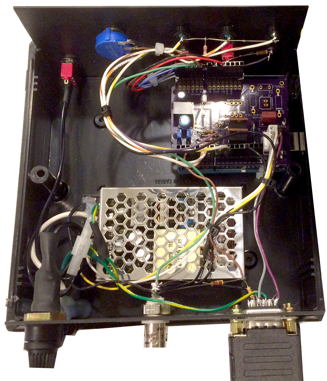
- Uses standard Arduino Uno (or clone) and most wiring is on a custom printed circuit board “shield”
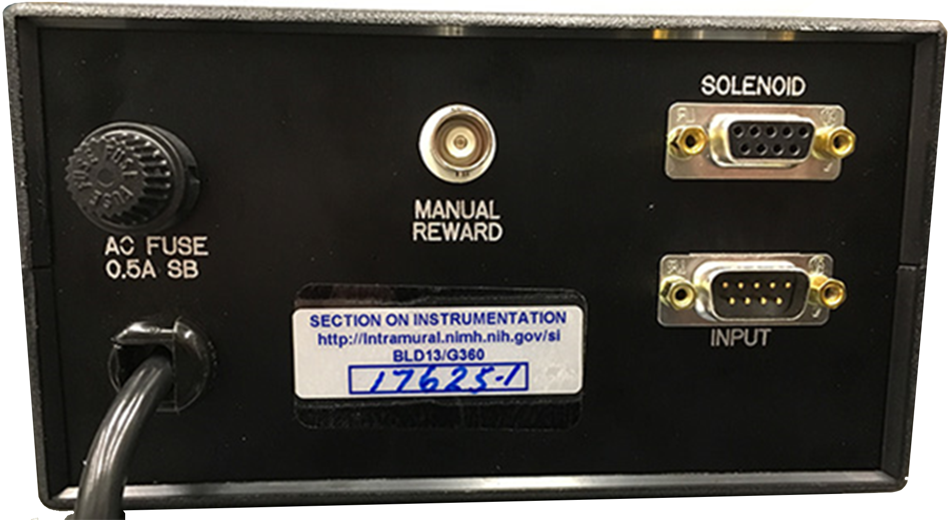
Connections (see Rear Panel Close-up View)
a. MANUAL REWARD (BNC connector)
This can be connected to a push button (“normally open”) to deliver “free rewards”. The MILLISECONDS control on the front panel determines the amount of reward by controlling the valve opening time.
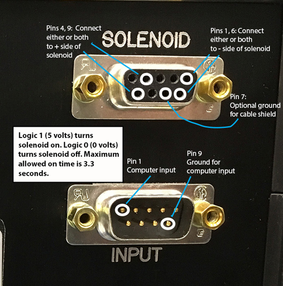
b. SOLENOID (9 pin female connector)
This connects to a 24-volt liquid solenoid or pump motor. Pins 4 & 9 connect to the positive (+) terminal of the solenoid. Pins 1 & 6 connect to the negative (-) pin of the solenoid. Two pins are provided for each side of the 24 volts. Either or both pins can be used. Pin 7 is a ground that can be tied to the shield of a shielded cable to reduce noise generation. See close-up view.
c. INPUT (9 pin male connector)
This connector receives the reward pulse from the computer. Normally, pin 1 is the input from the computer and pin 9 is the ground. The computer input can be moved from pin 1 to a different pin (usually 2 or 3). This is common when multiple juice reward devices are in use. See close-up view.
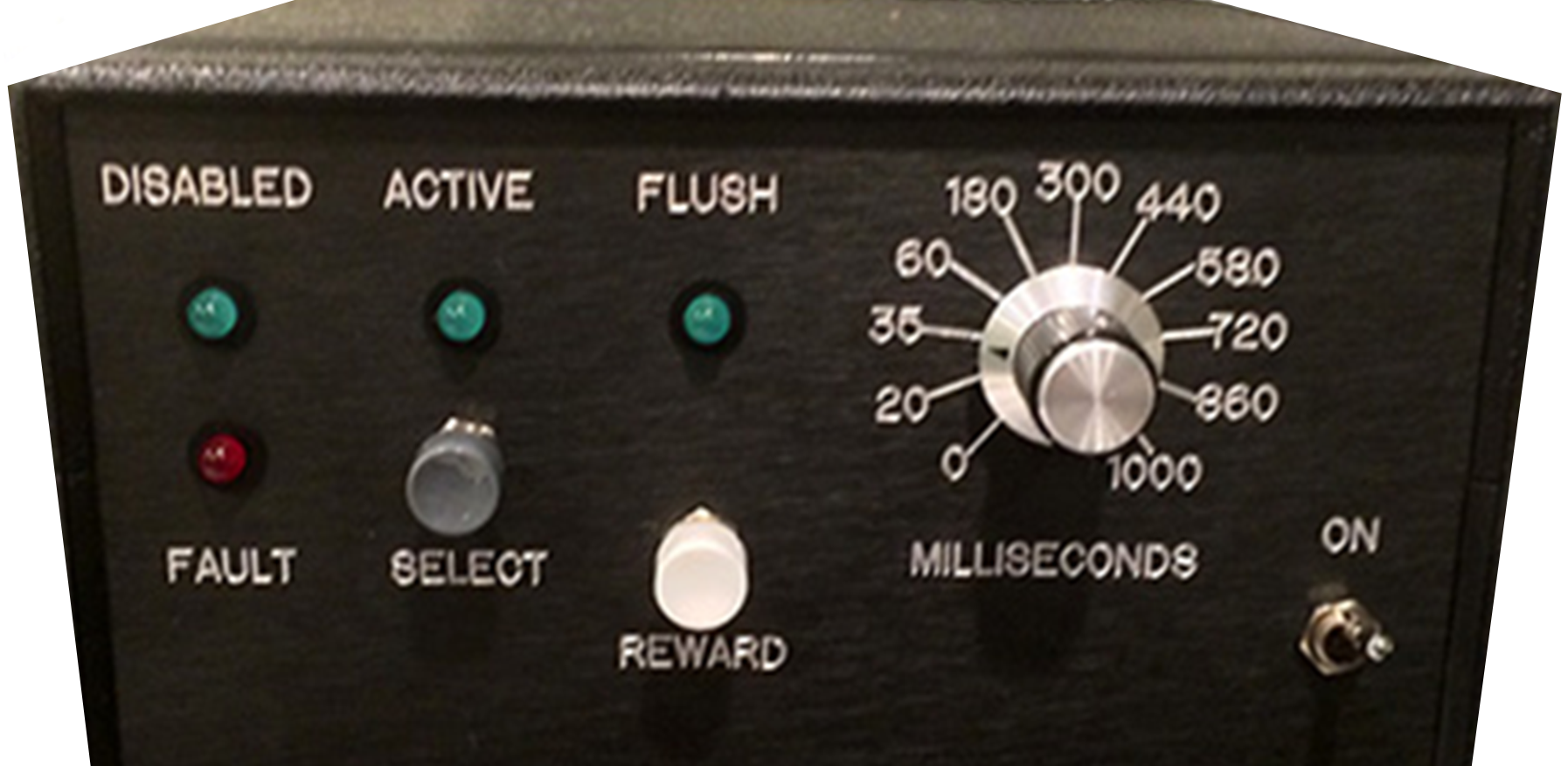
Basic operation
The Driver has 3 modes indicated by 3 green LEDs. Use the SELECT button to choose the mode you want.
a. DISABLED
No rewards can be delivered in this mode. This is especially helpful to prevent unwanted rewards during setup of the behavioral control computer.
b. ACTIVE
In this mode, rewards can be delivered by direct connection or wirelessly by the computer, the front panel REWARD button or a pushbutton connected to the BNC connector on the back panel.
c. FLUSH
In this mode, pushing the front panel REWARD button starts a flush. The solenoid is turned on for 30 seconds. The flush ends automatically. If the flush is running, a second push of the REWARD button will end the flush. Switching to another mode will also end the flush. (The 30-second flush time can be changed in the software. See the SOLENOID_CLEAN_PERIOD variable.)
Some solenoids have pistons that get stuck when sugary liquids are used. You can clean the piston in the FLUSH mode (before the piston gets stuck). Flush the tubing first. Make sure there is still some water in the system. While in the flush mode, push and hold the SELECT pushbutton (not the FLUSH pushbutton) for 1.5 seconds. When you release, the solenoid will cycle on-off at once per second (10 ms on, 90 ms off) for 30 seconds. Clean water in the tubing will wash sugar out of the piston.
Fault (Red LED)
If the direct computer input gets stuck on for more than 3.5 seconds, or a Bluetooth reward command is issued for more than 3.5 seconds of reward, when in the ACTIVE mode, the Driver will disable itself and the red FAULT LED will start flashing. Use the SELECT button to go back to ACTIVE operation. The purpose is to prevent computer problems from locking the juice valve open. If you need to deliver rewards longer than 3 seconds, the Smart Solenoid Driver must be re-programmed for a longer fault time. (See the value assigned to COMPUTER_ERROR_TIMER.)
If the unit keeps faulting unexpectedly, something is wrong with the computer input to the Smart Solenoid Driver. If the computer is off, the computer input is not connected, or the computer I/O board is not producing a digital output, a fault may occur. That is because the computer input circuit of the Smart Solenoid Drive is relatively high-impedance and can be triggered by noise. If using Bluetooth for rewards, we recommend connecting Pins 1 and 9 of the Input connector together. This will short out any noise that may accidently trigger the direct input.
MILLISECONDS scale
Notice that the MILLISECONDS scale for manual rewards is not linear. The scale is compressed on the mid and high ranges to provide the most useful values in one turn of the dial. The scale is fairly accurate if the Smart Solenoid Drive is assembled using the recommended potentiometer. Remember that the computer control of the timing does not rely on the MILLISECONDS scale. The scale for manual rewards is not relevant to computer input.
Wireless (Bluetooth) operation
If a Bluetooth module is installed, the Smart Solenoid Driver will respond to text commands after pairing with a smart phone or computer. While a direct connection from the computer to the Smart Solenoid driver controls the reward duration with the duration of the computer-generated reward pulse, Bluetooth commands hand over the timing responsibilities to the Smart Solenoid Driver. The timing of pulses and pulse trains are managed by the Driver. A text string from the behavioral computer provides the following information:
- Solenoid number. One of six different solenoids can be triggered (solenoids are labeled A through F, and also numbered 1 through 6). Currently, our drivers support only one solenoid.
Any attempt to operate a non-existent solenoid causes an error. - Pulse duration.
- Number of pulses.
- Pause time between pulses when more than one pulse is delivered.
All of the information can be stored in memory before triggering a pulse. Alternatively, a single command can provide all the pulse information as well as trigger the pulse.
| The following commands can be used to store the information for future pulses. Command | Parameter | Notes |
|---|---|---|
| K | Integer | Solenoid number 1 to 6, Default is 1. |
| # | Letter | A to F corresponds to solenoid 1 to 6 |
| T | Integer | Reward duration in milliseconds. Default is 50 ms |
| N | Integer | Number of pulses to deliver. Default is 1 |
| P | Integer | Time between multiple pulses in milliseconds. Default is 500 ms |
Open source documentation
To download schematics, assembly notes, and all associated files, send an email to arm@nih.gov requesting access to directory smart_solenoid_driver.
Access to this directory requires an account on box.com . When requesting access to the directory, provide your email (registered with box.com ) and the name of the requested directory. When the email is received, your email address will be given access to the requested directory. You may request multiple directories in one email request.