

Stimulation and fMRI Synchronizer (SfS): for Fast Scan Cyclic Voltammetry
Description
The Stimulation and fMRI Synchronizer (SfS) tracks the scan cycle timing of a fast scan cyclic voltammetry (FSCV) recording system and provides stimulation and fMRI triggering output signals. The output signals can be programmed to avoid interfering with the FCV scans. This unit was designed to work with the most common apparatus for animal work, the UEI "Tar Heel" FSCV. However, a unique feature of the SfS is that it can also semi-automatically synchronize its internal clock with the WINCS wireless FSCV system , which allows synchronization in the absence of a direct timing connection.
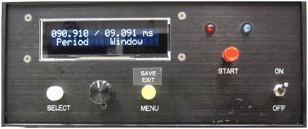
The SfS is a relatively small instrument (about 20 x 20 x 9 cm). The front panel has a two-line LCD text display that implements a simple menu system. Menu items are selected with a knob and two pushbuttons. A separate pushbutton starts stimulation events. A pair of LEDs help signal success or failure during stimulation. There are two inputs, one for the cycle timing signal from a directly connected FSCV (i.e., the CV FREQ signal from a UEI system) and the other is used to briefly measure the clock timing of a WINCS. There are three outputs to provide timing for electrical stimulation and fMRI triggering. The electrical stimulation output provides a trigger signal for each pulse in a stimulation train. The train pulses are not precisely uniform. Rather, the pulses are shifted to dodge or hit the voltammetry cycle window as described below. The trigger pulses are intended to drive a user-supplied stimulator and stimulus isolation unit. A second stimulation output provides a "gate" that is turned off just before stimulation begins and back on when the pulse train is over. fMRI trigging has a single output. When enabled, the output provides a brief (about 1 ms) pluse immediately after each voltammetry cycle. The SfS has a mode that uses fMRI triggers to discover and synchronize with the clock phase of a WINCS system.
Features
- Supports both wired (UEI "Tar Heel") and wireless (WINCS) voltammetry systems.
- Automatically measures FSCV scan cycle timing.
- Triggers brain (DBS) stimulators to avoid or include FSCV scans, with flexible control of stimulation pulse timing.
- Triggers fMRI scanning to avoid interference with FSCV scans.
- Designed to synchronized itself to a WINCS wireless FSCV, with minimal long-term drift.
Detailed Explanation
Fast scan voltammetry timing
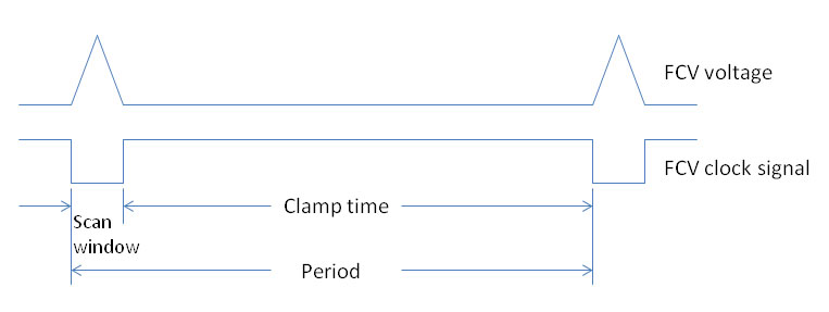
Timing of a typical fast scan cyclic voltammetry system
A typical FSCV cycle has a 10 ms scan window every 100 ms. If electrical stimulation or radio frequency interference (RFI) from a fMRI scan occurs during the scan window, it will introduce an artifact into the recorded voltammagram. The SfS can be programmed to deliver pulses that avoid the scan window.
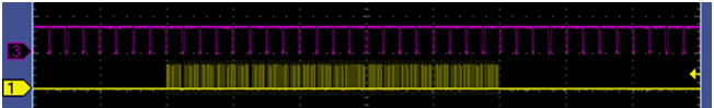
Screen 1
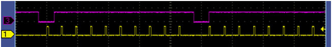
Screen 2
Oscilloscope Screen 1 (above) shows the timing of a 2-second stimulation pulse train (100 pps). The purple signal shows the voltammetry timing. The yellow trace is the stimulation timing. Screen 2 shows the fine structure of the same stimulation pulse train. Note that the first pulse interferes with the first scan. That is, the yellow pulse occurs while the purple signal is low. The second (and all subsequent) scans are free from stimulation interference, since the stimulation pulse has been shifted just outside the scan window. Interference with the first scan conveniently marks the voltammagram. Avoiding the other scans guarantees that the stimulation will not interfere with the response to stimulation. The SfS can flexibly control these timing features of electrical stimulation and/or fMRI triggering. The user sets the stimulation duration and the number of stimuli. The user also selects whether or not pulses can occur during a FSCV scan. The controller applies a series of huristics to determine the exact timing of the pulses.
Implementation
The SfS is based on a Microchip PIC32 USB Starter Kit II and Expansion Board, which uses a PIC32MX795F512L microcontroller. There is minimal additional hardware beyond the LCD, switches and a threshold detector chip (LMC6772B) for measuring the WINCS clock. The latest implementation has about 2,700 lines of MPLAB C (academic version) code complied on the MPLAB IDE v8 development environment set up as a Starter Kit application.
Documentation Download
Download a user manual
File name: sfs_user_guide.docx
To download this file, send an email to arm@nih.gov requesting access to directory: sfs
Access to this directory requires an account on box.com . When requesting access to the directory, provide your email (registered with box.com ) and the name of the requested directory. When the email is received, your email address will be given access to the requested directory. You may request multiple directories in one email request.